Text: Hideyuki Goto
This is the fourth in a series of articles explaining the procedure for installing KITACO's 164cc NEO Bore Up KIT on an early model Honda Grom 125 (2013-2017). The disassembly process was completed with the removal of the cylinder and piston in the previous installment. Now it is time to start installing the bore-up kit. First, piston rings are set on the pistons, and then the pistons are assembled to the connecting rods. The piston rings and piston pin clips used to hold the pistons in place are under tension during this process, so they can be accidentally blown off during installation. It is important to proceed with the work carefully, because if they are skipped, the parts may be lost or damaged.

The kit to be assembled is KITACO's 164cc NEO Bore Up Kit. In this case, piston rings are set on the pistons, and the pistons are assembled to the connecting rods.
Piston Ring Installation
The first step is to set the piston rings on the piston. The piston has three grooves dug into it, one for the top ring and one for the second ring, and the bottom oil ring consists of three rings: two side rails and one expander. The top and second rings have two sides, and are set so that the side with the engraving on the surface is on the front (top) side. The oil ring has no front or back, but is set with the expander between the side rails.

(1) Piston and its piston rings for the 164cc specification to be incorporated in this project. A total of five piston rings are required: a top ring, a second ring, and an oil ring consisting of three rings.

(2) Check the engraving on the top of the piston: "NEO" for NEO bore up kit, "164cc" for engine displacement, and "EX" for exhaust valve.

(3) Three grooves are engraved on the side of the piston; the bottom groove, where the oil ring, which consists of three grooves, enters, is thicker than the other two grooves.

(4) The two side rails that make up the oil ring. These side rails do not have a front and back, so there is no need to check them in particular.

(5) Expanders that make up the oil ring. Expanders are soft, so be careful not to bend them when handling them. There are no front and back sides.

(6) The expander is installed in such a way that it is sandwiched between two side rails. Instead of setting three expanders at a time, they are set in the piston groove one at a time.

(7) First, set one side rail into the bottom groove. Since the side rails are relatively soft, they are set into the piston by opening the joint.

(8) When setting piston rings on pistons, not only side rails, care must be taken not to scratch the pistons.

(9) Once the first side rail is placed in the bottom groove, set the expander on top of it. The expander is very soft and can be easily placed in the groove.

(10) The expander is set on the side rail. Check the piston all the way around to make sure it is firmly seated in the groove.

(11) Set the upper side rail. The groove is narrow and difficult to insert because of the two rings in the first place, so we need to work carefully.

(12) With the oil ring set. Be sure to check that the side rails, expander, and side rails are set in this order.

(13) The top ring and second ring are set. The way to distinguish the rings is by color: the silver one is the top ring and the black one is the second ring.

(14) Although it is difficult to see in the photo, there is an engraving on the surface of the ring at the end of the mating end. Set the ring on the piston so that this engraving is on the upper side.

(15) Set from the second ring. Since it is thicker and stiffer than the side rails, be careful how much force you apply when opening it.

(16) With the second ring in place, it is normal for it to enter the first groove, so even if it does, do not panic and pull it out to shift it into the second groove.

(17) Set the top ring. As with the second ring, check the engraving before setting the top ring to ensure that the front and back are correct.
Displacement of Piston Ring
Piston rings cannot just be set in a groove. It is necessary to shift the joints where the rings are cut, called "joints. Kitako specifies that the joints of the top ring, second ring, and expander should be shifted by 120 degrees, and that the joints of the side rails and expander should be shifted by 2 cm to the left and right.

(18) After all the piston rings are in place, shift the mating rings. (18) Once all the piston rings are in place, shift the mating ports. If the mating ports are in the same position, it is easy for pressure to be released and for oil to rise into the combustion chamber.

(19) Using the stamping on the piston top as a guide, shift the mating point by 120 degrees. The oil ring should be aligned at the mating point of the expander, and the side rails should be shifted 2 cm to the left and right from there.

(20) Drawing for piston ring installation. It is recommended to work according to this drawing for the piston ring setting position and shifting of the mating port.
Install piston pin clip on one side
The piston clip is stiff and must be shrunk under considerable tension to set it in place. Many people have experienced difficulties when removing the clips, but great care must also be taken when installing them so that they do not fly off. Before actually attaching it to the piston, it is a good idea to check how to apply force to successfully shrink it. Also, make sure that the piston pin clip is installed on the correct side before installing it.

(21) The piston clips are attached to the piston. In the case of a new piston, the piston pin clips are not set on both sides, so two piston pin clips are needed.

(22) The piston is set so that the exhaust valve side with "EX" is down, so the piston pin clip on the back side of the photo (left side when viewed from the front) is installed first.

(23) Before installing the piston pin clip, apply engine oil thoroughly to the groove where the piston clip fits.

(24) First, firmly grasp the piston clip near the mating end with the pliers and set the end of the mating end in the groove. Then, while pressing down with your thumb on the part of the piston pin clip that protrudes from the clip, apply force to the pliers as if you were turning the clip.

(25) A "snapping" sound is heard, and the piston pin clip fits into the piston groove. Since this is a part that is often blown off, you should be careful not to let it fly off, and of course, you should wear protective goggles or other protective gear when working on it.

(26) Rotate the clip to shift the position of the piston pin clip so that the notch in the piston is not the same as the mating point of the piston pin clip.
Piston Assembly
The surface of the piston pin and the inside of the piston pin hole where the piston pin contacts the piston pin should be well oiled so that the piston pin can be set easily and securely. Also, when setting the piston pin clip, care should be taken not to put a load on the connecting rod.

(27) Once the piston pin clip is set on one side, assemble the piston to the connecting rod with the piston pin.

(28) Apply engine oil thoroughly to the piston pin holes of the piston. The holes are located on both sides, so apply from the inside and outside to both holes.

(29) Apply engine oil to the piston pin as well. After dripping oil on the surface of the pin, spread it over the entire surface with your fingers.

(30) Insert the piston pin clip to some extent from the unset side so that the tip of the piston pin does not protrude inside the piston.

(31) Check the "EX" marking on the piston top and set the piston on the connecting rod so that this marking is on the lower side.

(32) Bring the piston to the end position of the connecting rod. Be careful not to bump it as it passes between the stud bolts.

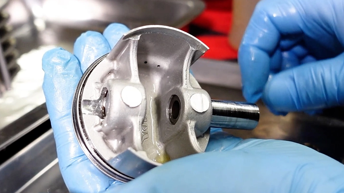
(33) Align the piston and connecting rod hole positions and push the piston pin in. If it is well oiled, you should be able to insert it deeply with your finger.

(34) The piston pin is in the deepest position. Make sure that the groove where the piston pin clip is set is completely visible.

(35) Set the piston pin clip to secure the piston pin. First, apply engine oil to the groove where the piston pin clip fits.

(36) Set the piston pin clip in the same manner as in processes (24) to (26). Be careful not to stress the connecting rod.

(37) Once the piston pin clip is installed, check that the clip is fully seated in the groove and that the mating portion is aligned with the notch.

(38) Pistons are assembled. Next time, the cylinder and cylinder head will be assembled.